FSAE-High-Voltage-System-Design-and-Optimization
Shutdown Latch PCB
Design
Rule
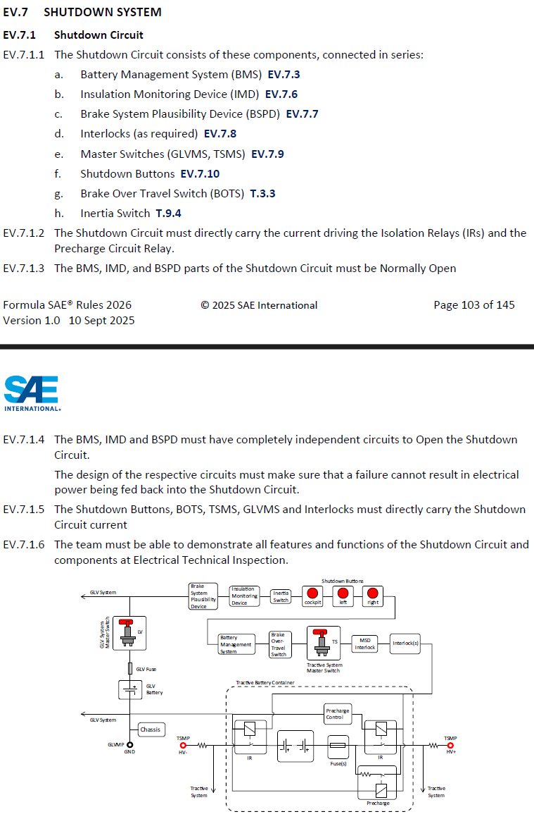
Figure 1: Screenshot of FSAE Rule EV.7.1
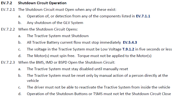
Figure 2: Screenshot of FSAE Rule EV.7.2
The purpose of Shutdown Latch PCB is to incorporate normally open and independent BMS, IMD and BSPD circuits as dictated by the rules shown in Figure 1, while opening the entire Shutdown Circuit when any of the three error signals is sent to the PCB as dictated by the rules shown in Figure 2.
Schematic
To fulfill the requirements set by the rule, the following schematic has been designed.
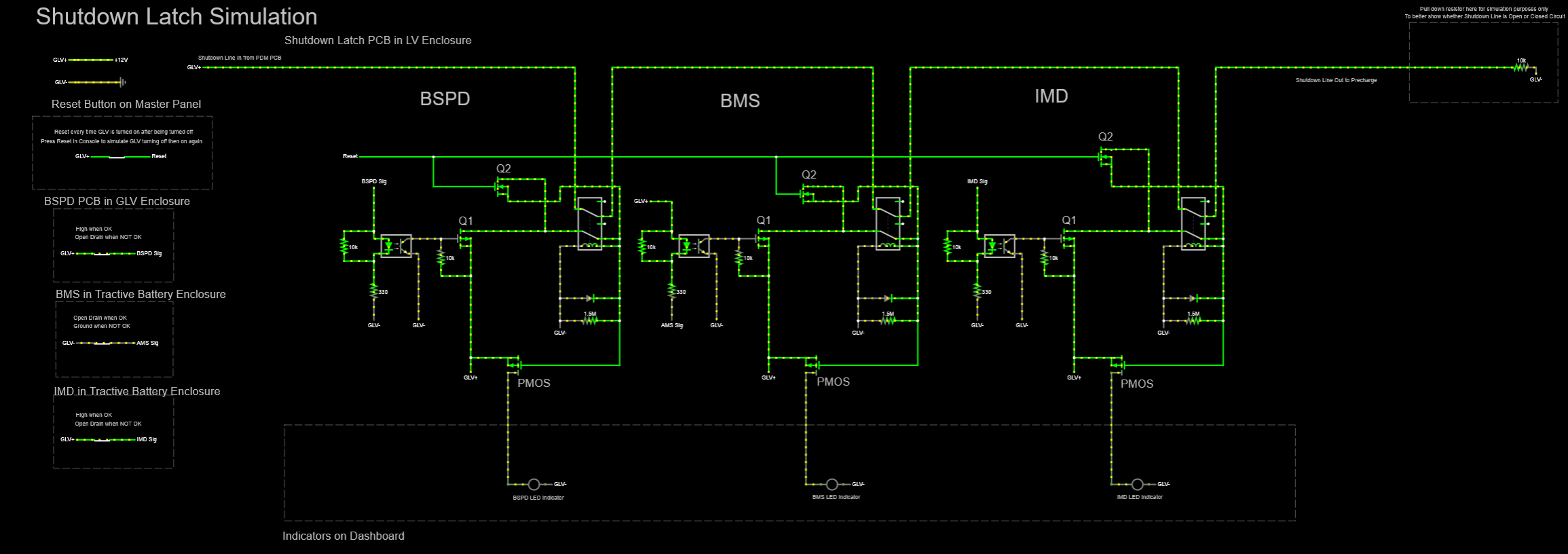
Figure 3: Shutdown Latch PCB Falstad Schematic
Summarise this section, it is too lengthy
The Shutdown Latch consists of a series of double-pole-single-throw relays which acts as series switches to in the shutdown line based on the BMS, IMD and BSPD. Each of the IMD, BPSD and BMS circuitry on the shutdown latch functions the same way.
When the car power cycles, the relays are by default open since there is no current flowing to the relay coils. Although Q1 is closed (assuming there is no fault), Q2 is open as the reset button has not been actuated. This also means that the shutdown line is opened whenever the car power cycles. If there is a fault, then the reset button will close Q2, but Q1 is opened and hence current is still unable to flow to the relay coil. Therefore, the reset button does not do anything if there is a fault in the IMD, AMS or BSPD. Since the PMOS gate is wired in parallel to the relay coil, when current is flowing through the relay coil, the voltage at the PMOS gate will be at GLV+, and when no current is flowing through the relay coil, the voltage at the PMOS gate will be pulled down to GND. The PMOS is used to power the LEDs on the dashboard, so when the relays coils are not powered – the PMOS is closed, and the LEDs are powered on the dashboard. The opposite is true as well.
If there is no fault, then to reset the Shutdown Latch, simply press the reset button to close Q2 and Q1 which allow current to flow to the relay coil. The relay is implemented such that one of the poles will take over from Q2 in powering the relay coil. The relay is latched on after the reset button is no longer actuated. If IMD, BSPD or BMS gives a fault, the optocoupler on the shutdown latch will be switched on, and Q1 gate will be pulled down to GND, discontinuing current flow to the relay coil. At the same time, the PMOS gate that is connected in parallel to the relay coil will be pulled down to GND as well, since Q1 is now an open circuit. This means that there is now current flowing through the PMOS towards the respective LEDs on the dashboard. If the fault signal changes from low to high, the only thing that is required to change is the way the optocoupler is implemented on the PCB.
Speccing Components
Simulation
Falstad
Explain how the schematic is being tested as per car start up sequence (refer to 26 Electrical Powertrain 101 for Falstad links)
Prototyping
Manufacturing
Interhorizon Pte. Ltd. manufactures PCBs for us, just briefly go through this section
Testbench
Mention car start up sequence and how we induced errors to check Shutdown Latch functionality
Testing and Validation
Test Run
Mention how the team was able to troubleshoot the car immediately thanks to dashboard indicators connected to Shutdown Latch
Technical Inspection
Talk about ESF & EV Active